Viewing OsciStudio output on a real oscilloscope


#1

Hello everyone,

I wish to connect a real oscilloscope to the computer to see on it the result of my sound files from Blender/OsciStudio

Can somebody tell me please, how to connect a real oscilloscope to the preamp that is hooked to my audio card.
What cables I need to use, please?

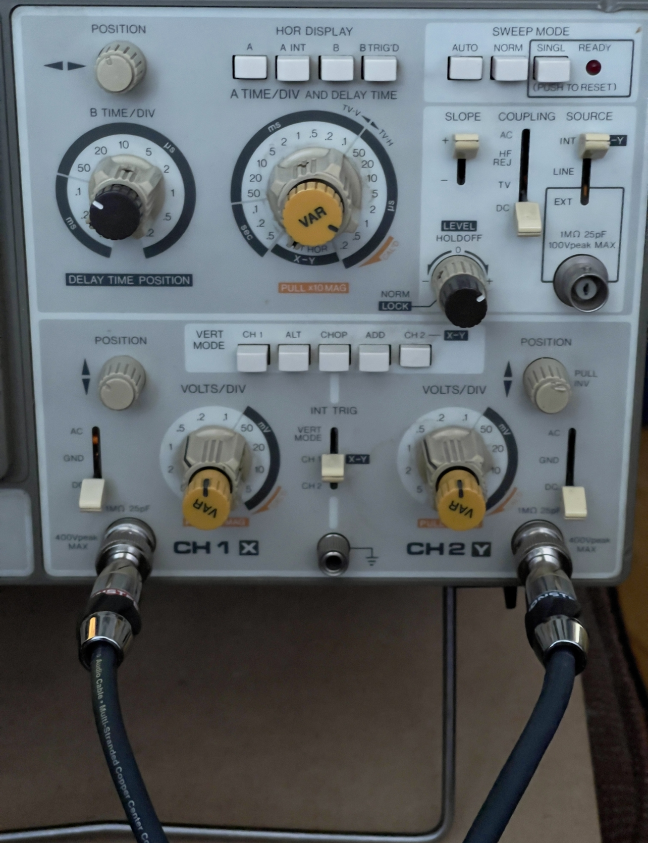
I have KIKUSUI OSC 5041 (not sure if that one could work). It also has XY mode, but I have no idea how to set up the whole thing properly.

Thank you in advance for your lights.

All the best to you all
Museek


#2

Hi, Check this link out. It is a group that all do osciloscopes and that sort of thing. see you there.
https://www.facebook.com/groups/vectorsynthesis/?ref=share


#3

hi!

can you post a picture of the oscilloscope?

Buying the cables

if you have stereo mini jack (3.5mm) output you want these cables:

if you have double jack (6.3mm) output you want to use these cables:

now you end up with 2 bnc adapters which you can hook up to almost all oscilloscopes.

Connecting the oscilloscope

The most common type of oscilloscope has a knob labeled “ms/div” (milliseconds per division), and the left most position will be labeled “X/Y”. That’s the mode you want to use.

  • The right channel goes into the deflection input, usually the first channel. If you’re lucky there’s a small “Y” written nearby.
  • The left channel goes into the “ext. trigger”. This might also be written as just “ext”, or if you’re lucky there’s a small “X” nearby.

There are a few oscilloscopes specifically made to work in X/Y mode. In this case it’s simpler

  • The left channel goes into the X input
  • The right channel goes into the Y input

#4

Awesome, thanks a lot for the link. See you there :slight_smile:


#5

Hi!
You’ve been very helpful. Thank you! I found the cable that works at home :slight_smile:
BNC adapters at local reseller.
After turning all the buttons like crazy, I finally could see the oscilloscope drawing figures on its screen.
Amazing! Felt in love.

That is funny, three days ago I saw someone on YouTube showing that oscilloscope can be used creatively for sound visualization.
I went to a local ebay-like platform immediately to see if someone is selling any oscilloscope. There was an auction ending within an hour. :smiley: 
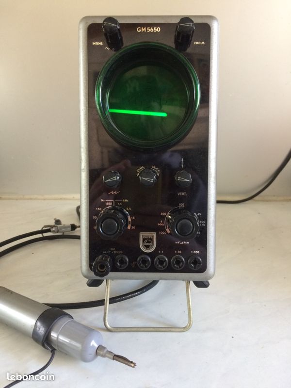
I won it and here I am all in.

Thanks again for your help!


#6

Photo 1 (as a new member, I am limited to one photo per post, so here we go)


#7


#8

Yet, I would like to ask, Is there on this forum or elsewhere a place that list all tools (apps, hardware and so) that helps create sounds and animations for oscilloscopes?

thanks!


#9

it’s a bit all over the place. there’s a list of some related software at the end of this page: https://www.oscilloscopemusic.com/software.php

for discussions there are at least two places i know of https://www.reddit.com/r/oscilloscopemusic and https://www.facebook.com/groups/vectorsynthesis


#10

Thanks a lot for your links. Very helpful.


#11

Hi, Can you confirm this model works please ?
I don’t see XY fonction on it 
 only Vertical ??
Thanks a lot for your works


#12


#13

@qix did you figure it out?

if not, the subreddit might be a better place to ask (and please add another picture straight from the front showing the whole front panel) reddit.com/r/oscilloscopemusic/


#14


#15

huh. it’s beautiful, but far from normal :smiley: first things first:

i’m not sure this supports xy mode at all!
and not just me, there is some discussion here, and most people believe it’s a 1-channel scope (you need 2-channel for xy) see this post: https://www.sequencer.de/synthesizer/threads/oszilloskop-anschliessen-wie.157931/

here is the manual in dutch: https://www.opweb.de/deutsch/firma/Philips/GM_5650
page 10 in the pdf is the interesting one.

and here are nice pictures: https://www.radiomuseum.org/r/philips_oszillograph_gm5650gm_565.html

i can only guess dutch, if at all, it might work like this:

connect the left channel to BU1 (gnd) and BU2 (signal), and the right channel to BU3 (gnd) and BU4 (signal). Little warning: DO NOT CONFUSE GROUND AND SIGNAL!

then turn the switch R4 to “Sync”, move R3 and R5 to center position, and play around with SK2 and SK3. what do you get?


#16

ps. sadly i believe it’s not going to work. i just noticed in your image it’s already in the “SYNC” setting, so you should get a dot and not a line if xy would work this way.


#17

Yes, it’s sadly not work

Thanks for your times